


One Touch, Friend Forever
contact sales at SINOWON.
The FAQ of Rockwell Hardness Tester
Q1. Who did invent Rockwell testing method for the material testing?
Answer: It is acceptable that Mr. Hugh M. Rockwell (1890–1957) and Mr. Stanley P. Rockwell (1886–1940) from Connecticut in the United States co-invented the "Rockwell hardness tester," a differential-depth machine. They applied for a patent on July 15, 1914.[4] The requirement for this tester was to quickly determine the effects of heat treatment on steel bearing races. The application was subsequently approved on February 11, 1919, and holds U.S. Patent 1,294,171.
Q2. What is difference between Rockwell and Superfical Rockwell?
A fundamental distinction is made between two types of Rockwell method: Regular Rockwell (or Rockwell) and Superficial Rockwell (or Super Rockwell):
• Rockwell: The pre force (or preload) is always 10 kgf, while the total test force (also referred to as main force or load) can vary between 60, 100, or 150 kgf.
• Super Rockwell: The pre force is 3 Kgf, while the main force can vary between 15, 30, or 45 Kgf.
| Test methods | Rockwell | Super Rockwell | ||||
| Preload force | 10kgf | 10kgf | 10kgf | 3kgf | 3kgf | 3kgf |
| Main force | 150kgf | 100kgf | 60kgf | 45kgf | 30kgf | 15kgf |
The hardness values determined by Super Rockwell can be converted to Rockwell values and vice versa. The Superficial Rockwell method was invented in the USA, where its use is significantly more common than in Europe. It is particularly suitable for use in hardness testing of thin components and layers, or with specimens whose calculated hardness value is outside the Regular Rockwell scale.
Rockwell and Superficial hardness testing shall be performed in accordance with the latest revision of ASTM E18.
There are two general classifications of the Rockwell test: the Rockwell hardness and the Rockwell superficial hardness test. In the Rockwell hardness test the preliminary test force is 10 kgf. Total test forces are 60 kgf, 100 kgf and 150 kgf. In the Rockwell superficial hardness test, the preliminary test force is 3 kgf and total test forces are 15 kgf, 30 kgf, 45 kgf. The indenter of either test shall be of spheroconical or spherical configuration The standard indenters are the diamond spheroconical and tungsten carbide ball indenters' 1/16, 1/8, 1/4, 1/2 inch in diameter. Annex 3 or A3. STANDARDIZATION OF ROCKWELL INDENTERS, covers the requirements of indenters to be used. The dust, dirt, grease and scale shall not be allowed to accumulate on the indenter as this will affect the test. Anvils used for indention’s must be suitable for specimen. Cylindrical pieces shall be tested with a V-grooved anvil Flat pieces shall be tested on a flat anvil, whose plane is perpendicular to the axis of the indenter. The anvils shall be clean and smooth and free from pits, scratches, dust, dirt and grease. The anvil and indenter shall be set properly by running two tests not used in calculations.
The test specimens shall be clean and prepared in a way that alteration of the surface hardness is minimized. Flat specimens' surfaces should be flat and parallel to indenter and anvil. The thickness of the test piece or of the layer under test should be as dictated in Table 7, 8, 9, and 10 of ASTM E18. The general rule, is the thickness should be 10 times the depth of the indenter. For tests on convex cylindrical surfaces the corrections given in Tables 11, 12, 13, and 14 of ASTM E18 shall be applied.
Place the specimen on the proper anvil and bring the indenter in contact with specimen until the machine engages the minor load. This indicates machine is ready for reading and will give automatic readout. There should be a minimum 3 readings per sample and 4 readings for bolt testing. Each reading should be a distance of three times the diameter of the indenter apart. Take an average of the readings for the final result. If technician believes that a reading is not representative of material an additional 3 readings can be used to replace the one.
Before each test using a different scale, start of a day, or change of indenter the machine will be calibrated using NIST traceable hardness blocks. This calibration will be logged and recorded using hardness block limits with an average of three readings for each test block. After testing the final report will include Rockwell hardness number, scale used, and readings to nearest the whole number by rounding in accordance with ASTM E29.
Q3. What is difference between Rockwell and Superfical Rockwell?
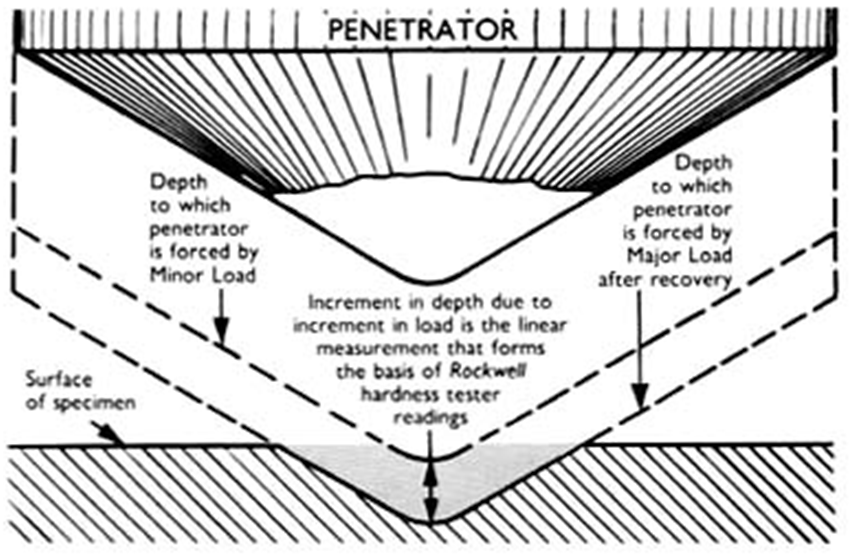
In Rockwell testing, hardness is determined by measuring the comparative depth of two carefully controlled indentations, one superimposed over the other.
First a Minor Load (one of a lesser force) is applied to a steel ball or sphero—conical diamond penetrator. Then, while the Minor Load is still being applied, a Major Load (one of greater force) is applied at a precisely controlled rate. The Major Load is removed and the hardness determination is displayed.
The hardness determination obtained represents the additional depth to which the Major Load has indented the test specimen beyond the initial indentation of the application of the Minor Load. The displayed indication is proportionally inverse, e.g. the higher the displayed determination of hardness, the shallower the indentations, therefore the harder the material.
In the regular (R) Rockwell scale, the Minor Load is is 10 kgf and the Major Load may be 60, 100, or 150 kgf. In the superficial scale (S), the Minor Load is 3 kgf and the Major Load may be 15, 30, or 45 kgf.
To ensure accuracy and consistency, the Major Load is under precise control and the penetrators are manufactured to specific tolerances. Each point of hardness on the regular (R) scale is 0.00008 inch and 0.00004 inch on the superficial (S) scale, making the need for precise control of the applied forces and precision manufacture of the penetrators readily apparent.
Rockwell Regular Scales
| ROCKWELL (R) REGULAR SCALE APPLICATIONS | |||
| Scale Symbol | Penetrator | Major (Minor) Load | Typical Application |
| A | cone diamond | 60 kgf (10 kgf) | • cemented carbides • thin steel • shallow case hardened stee |
| B | 1/16" Ball | 100 kgf (10 kgf) | • cooper alloys • soft steel • aluminum alloys • malleable iro |
| C | cone diamond | 150 kgf (10 kgf) | • steel • hard cast iron • perlitic malleable iron • titanium • deep case hardened stee |
| D | cone diamond | 100 kgf (10 kgf) | • thin steel • medium case hardened steel • perlitic malleable iron |
| E | 1/8" Ball | 100 kgf (10 kgf) | • cast iron • aluminum alloys • magnesium alloys • bearing metal |
| F | 1/16" Ball | 60 kgf (10 kgf) | • annealed copper alloys • thin soft sheet metal |
| G | 1/16" Ball | 150 kgf (10 kgf) | • phosphor bronze • beryllium • cooper • malleable iron (G92+ will damage penetrator) |
| H | 1/8" Ball | 60 kgf (10 kgf) | • zinc • lead • aluminum |
| K | 1/8" Ball | 150 kgf (10 kgf) | • bearing metals • relatively soft • thin materials • plastics (refer to ASTM D7851) Use the smallest ball and highest force that do not give "anvil" effect |
| L | 1/4" Ball | 60 kgf (10 kgf) | |
| M | 1/4" Ball | 100 kgf (10 kgf) | |
| P | 1/4" Ball | 150 kgf (10 kgf) | |
| R | 1/2" Ball | 60 kgf (10 kgf) | |
| S | 1/2" Ball | 100 kgf (10 kgf) | |
| V | 1/2" Ball | 150 kgf (10 kgf) | |
1 ASTM D785 (Vol. 08.01) Standard Test Method for Rockwell Hardness of Plastics and Electrical Insulating Materials
Rockwell Superficial Scales
| ROCKWELL (S) SUPERFICIAL SCALE APPLICATIONS | |||
| Scale Symbol | Penetrator | Major (Minor) Load | Typical Application |
| 15N | cone diamond | 15 kgf (3 kgf) | Superficial scale is ideal for testing materials that do not have sufficient width or thickness to be tested on the Regular (R) Rockwell Hardness Scale, these are typically: • very thin sheet metal • strip metal • wire • small rounds • nitride steel • lightly carburized steel • heavily cyanided steel • tin plate • other similarly configured specimens or materials. |
| 30N | cone diamond | 30 kgf (3 kgf) | |
| 45N | cone diamond | 45 kgf (3 kgf) | |
| 15T | 1/16" Ball | 15 kgf (3 kgf) | |
| 30T | 1/16" Ball | 30 kgf (3 kgf) | |
| 45T | 1/16" Ball | 45 kgf (3 kgf) | |
| 15W | 1/8" Ball | 15 kgf (3 kgf) | |
| 30W | 1/8" Ball | 30 kgf (3 kgf) | |
| 45W | 1/8" Ball | 45 kgf (3 kgf) | |
| 15X | 1/4" Ball | 15 kgf (3 kgf) | |
| 30X | 1/4" Ball | 30 kgf (3 kgf) | |
| 45X | 1/4" Ball | 45 kgf (3 kgf) | |
| 15Y | 1/2" Ball | 15 kgf (3 kgf) | |
| 30Y | 1/2" Ball | 30 kgf (3 kgf) | |
| 45Y | 1/2" Ball | 45 kgf (3 kgf) | |
Rockwell Carbide Scales
Scale C (carbide) testers are used for testing cemented carbides in the Rockwell A Scale, where tolerances of ± 0.20 of a Rockwell Hardness point are required. A specially selected "A" Brale penetrator is used to measure the hardness of cemented carbides in accordance with ASTM B 294 and the Cemented Carbide Producer's Association (CCPA).
In addition to the 60 kgf Major Load required for carbide A Scale testing, the Scale C testers also include 100 and 150 kgf capabilities.

Your Precision, Our Mission
Call Us
Tel: 0086-0769-23184144
Mobile: 0086-13728288444
Copyright © 2018 Sinowon Innovation Metrology Manufacture Limited. | All Rights Reserved 粤ICP备16062806号
Hello, please leave your name and email here before chat online so that we won't miss your message and contact you smoothly.

