


An ordinary day for Croce Rossa Italiana team leader Giulia to fight against the novel coronavirus
raspberry pi zero hdmi / wifi soldering microscope
by:Sinowon
2020-04-24
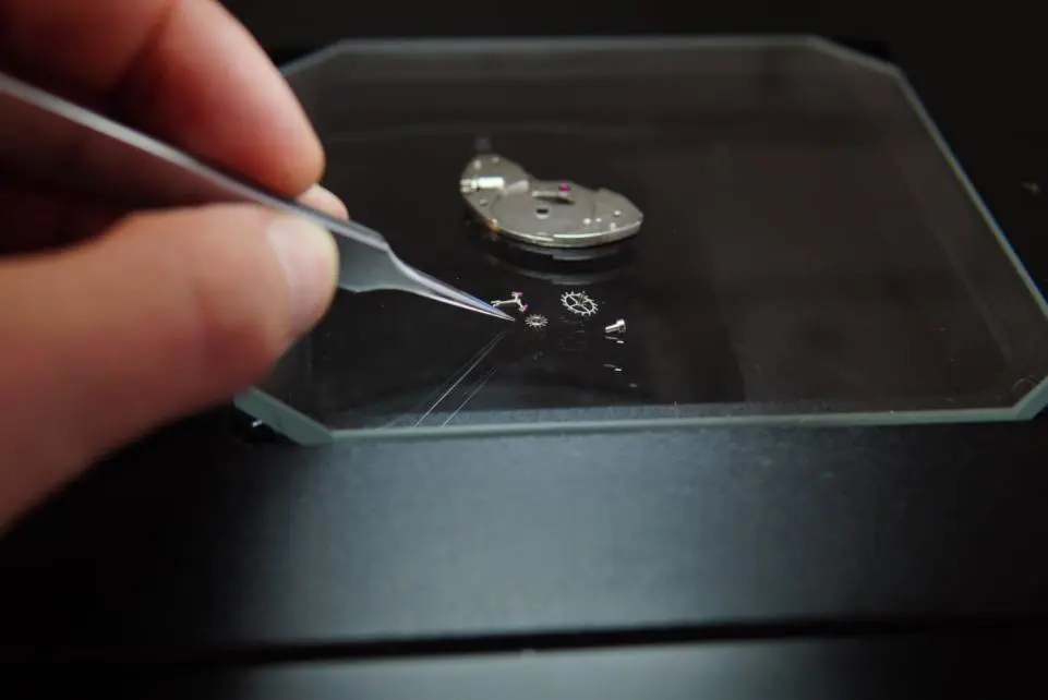
Soldering SMD components can sometimes be a bit difficult, especially in cases like 0.
4mm pin spacing TQFP chip with 100 or more pins.
In this case, it may be very helpful to get some kind of amplification effect.
To solve this problem, I decided to build my own welding microscope based on Raspberry Pi Zero W and camera module.
The microscope is able to transfer the full HD video directly to the HDMI display with little delay, which is perfect for soldering.
And via WiFi, the delay is less than half a second, which is very good for board checking.
Alternatively, the microscope can also be portable with just a little more money, combined with the WiFi video streaming feature, opening up an extra dimension for potential use cases.
If you happen to have a 3D printer, be sure to take a look at the amazing project of richw36 on Thingiverse and see the microscope version of the part using 3D printing!
To build a microscope, you need the following sections: 1 x Raspberry Pi Zero W [10€]
1 x [Raspberry Pi camera module]8€]-
In order to change the focal length of it, you need to crack it so that it can focus on an object close to it.
I don\'t know if the new 8MP camera module can do the same program as well, so I would suggest switching to the original 5MP instead.
1 x Raspberry Pi Zero camera cable [2€]-
As you may already know, Raspberry Pi Zero has smaller camera connectors than other Raspberry Pi boards, so you also need a special adapter cable to connect the camera module to it.
1 x plastic cents-
The cheaper you can find the better, I just used an old plastic simulation that I lay down.
1 x-
The ruler width must be less than the length of the clamp to move the lower jaw.
As for the length, it should be OK about 10 cm to 15 cm.
1x Aluminum Engineering Box 【4€]-
This will be used as the base of the Assembly and it needs to be made of metal so it will also be heat resistant.
The reason for the need for the box is that in order to be more stable during welding, you can put a weight in the box.
1 x HDMI cable and female HDMI to male mini HDMI adapter-
You can also buy HDMI to mini HDMI cable if you want, but I already have a normal HDMI cable.
1 x micro USB power-
According to my measurements, even if 400 mA p video is transmitted through WiFi and HDMI at the same time, the current drawn by the Pi will not exceed 1080.
So even 500 mA of the power supply should be enough.
Although I would recommend buying a version 1A, for the sake of security, especially if you are planning to build a portable version, this can also be lost on the boost converter.
1 x MicroSD card [5€]-
Even the 4 gb is enough, just make sure it\'s level 10 with high quality.
4 x M2 screw nut 【less than 1€]-
Large diameter screws can also be used.
Nevertheless, the larger the screws, the wider the holes needed, and the grater has the risk of plastic breakage.
1 x Hot glue bar 【1€]Cable Zip Ties[less than 1€]-
These will be used to attach the Pi to the moving part of the calipers.
And the following tools: hot glue GunA Dremel-
There is a disc that can go through the plastic, plus a plastic and aluminum drill bit of the screw size.
A long, flat nose.
You need a way to cut the screws on the right length.
I am using a pair of bolt cutting pliers, although I believe there are other tools available to do the job.
If you want it to be portable, you need the following additional parts: 1 x LiPo battery [8€]-
Its capacity will depend on the battery life you want, the efficiency of the boost converter and the average power consumption.
1 x LiPo battery charger/5 v boost converter [20€]-
For this project, I select PowerBoost 1000C from Adafruit.
There are cheaper alternatives on EBay as well, though I decided to pick that one because it has a good feature that I\'ll talk more about later. 1 x 40-
Double-row needle head 【less than 1€]1 x 40-
Female row needle with double row needle 【less than 1€]1 x 8-
Sales head 【less than 1€]1 x 8-
Sales head 【less than 1€]
1 x prototype plate [1€]-
Since you have to weld pin heads on both sides of the board, I suggest you buy a double sided one.
Alternatively, you can get a prototype board specifically designed for Pi Zero from MakerSpot, for example.
1x1 k resistance [less than 1€]
1x10 k resistor 【less than 1€]1 x BC547[less than 1€]-
I\'m using any kind of general-purpose drain transistor.
1 x DPST instant switch [1€]-
Ideally, you need the DPST switch, so you can turn the Pi on and off using the same button.
Unfortunately I don\'t have one around me so I have to use two separate SPST instant switches. Cable Zip Ties[less than 1€]-
The portable version also requires a battery for connecting the battery to the back of the prototype board.
Solder wire and the following additional tools: total cost of solder wire IronA pair wire cutting machine non solder wire
Portable versions that do not include power supplies, HDMI cables and mini HDMI adapters are about 30 euros.
In addition, the additional cost of making a portable phone is also around 30 euros.
Most of the parts are purchased on eBay.
Burning the image to a microSD card as the basis for the system, I decided to use the official Raspbian Lite image and then just install what I need.
What\'s going on, download the latest image of Raspbian raspberrypi Lite first.
Burn it to a microSD card.
If you are running Linux, after decompression, you can burn it by running the following command as root, where X is the letter of the device corresponding to microSD e. g. c.
Before running the command, make sure that there is no partition installed for the microSD card.
If you have to uninstall each of them using the following command, but be very careful here, replacing X with the wrong letter can cause irreversible damage to your system and ruin your day.
Before running the dd command, please double check if the letters you type in place of X really correspond to the microSD device.
If you are using Windows, after downloading the Raspbian Lite image and decompressing it, you can burn it on a microSD card using win32disk imager.
More information can be found in the official Raspberry Pi Documentation.
On MacOS there is a graphic app called Etcher that can be used to burn images on microSD cards.
Alternatively, you can also use dd similar to Linux, but the process is a bit different.
Again, you can check the official documentation for more information.
Configure WiFi after burning image to microSD card, you need to configure WiFi before the first boot and enable SSH.
The first thing you need to do is create an empty file named SSH in the boot partition of the microSD card.
If you are on Windows, the boot partition is most likely the only one you can see because Windows cannot read or write to the ext4 partition locally.
If the microSD card partition is not currently installed, simply unplug the card and plug it back into the computer.
Then, again, create a file named wpa_supply inside the boot partition.
Conf with wireless settings.
The contents of the file should be similar to this, proto can be RSN of WPA2 or WPA of wpa1.
Key _ admin can be WPA-PSK, or WPA-
EAP for enterprise networks.
Pairs can be CCMP of WPA2 or TKIP of wpa1.
Auth_alg may open, while LEAP and SHARED are other options.
As for the country, ssid, and cpp, these should be self-explanatory.
That\'s it, now just uninstall the microSD card from your computer and put it into your Pi.
Next, plug the Pi into the HDMI display, plug in the camera module using a special ribbon cable, and finally power on.
After a few seconds, the Pi should be up and connected to the WiFi network automatically.
On the screen, you should also be able to see the IP address it gets from the DHCP server of the router.
Update 4/6/2018: If your Pi is unable to connect to WiFi during startup for some reason, try the following wpa_supply.
Instead of Conf, I recently tried to set up a headless Pi Zero W with the latest version of Raspbian, and I wasn\'t able to get it to work until I used wpa_supply.
Conf provided above.
So it might help if you seem to have the same problem.
If you haven\'t connected the monitor to your Pi yet and you can\'t see what IP address it has, there are several ways to discover it.
One way is to check the logs of the router DHCP server.
Each router is different so I will not describe the process.
On Linux, another simple way is to run the following nmap command as root, where x. x. x.
X is the IP address of your dedicated network. g. 192. 168. 1.
0, y is the number of 1 (in binary)
Network shielding e. g.
For network shielding 255. 255. 255.
The number of 0 is 24.
So for the specific network you are going to run, the sample output of this command is as follows, and in my case you can see that the IP address of the Pi is 192. 168. 1. 4.
If you are on Windows, you can also try the version of nmap, you can find more information here.
After you get the IP address of the Pi, you can SSH to it using the following command on Linux and MacOS, or use PuTTY on Windows.
The default password for the Pi user is raspberry.
The system is almost completely unconfigured at the first launch, so you need to do some tasks first.
The first thing you need to do is change the default password for the pi user and then, you have to configure the locale.
You can do this by running the following command and continue to select all en_US locale using the space bar and any other locale you want.
Click enter when you finish.
Finally, choose en_US. UTF-
8 as the default locale and click Enter.
Next, you need to configure the time zone, it may be a good idea to update the system at this time, and next, you need to use raspi-
Configure the command, select the interface option from the menu, and then select the camera option.
Answer yes to the question asking you to enable the camera and select OK \".
Finally, select finish and answer yes to the question about whether to restart the Raspberry Pi now.
After restarting, reconnect to the Pi in the same way as before via SSH.
To test if the camera is working, you can run the following command, you should be able to see the video feed on the HDMI display, you can stop it at any time by pressing Ctrl-C.
You can also use-vf and -
The hf flag can flip the image vertically and/or horizontally if needed.
The next thing you need to do is set up a static IP address for your Pi.
Do this using nano edit your/etc/dhcpc4.
Conf, and add the following line at the end, in the domain _ name_servers settings, you can add multiple name servers divided by spaces if needed, E. G. g.
You can also add the IP of Google DNS, which is 8. 8. 8.
8 used as a backup server. Hit Ctrl-
X exit, type y, and finally click Enter to save the changes.
Then restart the dhcjdbc and network service by running the following two commands, at which point the SSH session should hang.
Don\'t worry, because you just changed the IP of the Pi, so this is expected, just reconnect to it via SSH, but use the IP you assigned this time.
There are several ways to stream video from Raspberry Pi over the network, but the way to provide a minimum delay is to use GStreamer.
To install GStreamer, you can simply run the following command, which has a lot of dependencies, so it will take a while.
After the installation is complete, you can transfer the video feed of the camera at the same time through the network and HDMI, using the following command, which will create an RTP stream on port 5000, by using GStreamer, any machine on the local network can receive the stream, and installing GStreamer on any machine running a Debian-based Linux distribution is exactly the same as on the Pi. Most major non-
The Debian-based distribution should also have GStreamer in their repository.
GStreamer is also available on Windows and MacOS, details on how to install it can be found here and here.
Of course, with the previous command, you can start the stream at any time, although this requires connecting to the Pi first via SSH, which is not very convenient.
Instead, what you want to do is create a script that will run automatically when started as a service and start the stream.
So to do this, first create a file using nano and then inside paste the following two lines,vf and -
Flip the image vertically and horizontally using the hf logo.
Depending on the direction of the camera after installation, you may or may not need them. Hit Ctrl-
X exit, type y, and finally click Enter to save the changes.
Then make the script executable by running, then you need to create a initempirical mode d service file and paste it into the following line, save the file and exit the nano, if everything is OK, run the following command to test your service, then you can run the following command to make the service start automatically at startup, usually a big problem with SD cards and flash memory is that they are easily damaged.
The best way to solve this problem is to install all the partitions of the microSD card as read-only.
This will also allow you to unplug the power from the Pi at any time without having to start the proper shutdown, which is very useful for such an application.
The first thing you need to do is delete some packages by running the following command, next you need to replace the rsyslog with the syslogd daemon of busybox, this daemon allows the system logs to be kept in memory and run to remove any packages that are no longer needed.
After that, you will be able to view the system log at any time using the logread command.
Next, you need to move/etc/resolv.
Since it needs to remain writable, it will be installed on memory.
The other file that needs to be writeable is/var/lib/initempirical mode d/random-
Again, because random seeds
The seed file is often not created at startup, and the content of/tmp is unstable, you need to change it by modifying the system\'s service filerandom-
Seed service file.
So, by using the nano, just add a row at the end of the service section and run like this to reload the initempirical mode d service file.
Next, you will need to edit the/etc/fstab file and add the ro option on the/dev/mmcblk0p1 and/dev/mmcblk0p2 partitions so thatonly on boot.
Also, add a few lines in order to install/tmp,/var/log, and/var/tmp in memory.
After making these changes, your/etc/fstab file should be similar to this, and finally, edit your Lastline.
Txt, and add the option fastboot noswap ro at the end of the line in order to disable file system check, disable swap, and force the file system to install as Readonly.
After that, your/boot line.
Txt should look similar to this, and finally, restart the system for the change to take effect.
After restarting, if everything runs as expected, in both cases, you should be given a \"read-
Only file system \"error.
Now you can unplug the power from the Pi at any time without getting the file system on the microSD card corrupted.
If you need to make the root file system temporarily read for some reason-write, e. g.
To install some packages, you can use the following command to install them, and after you finish, run the following command to make them read-
Again, if you want to make an update, make sure to load/boot and/as read-at the same time-
Because updates to the kernel and firmware are also written to the/boot partition.
At this point, we have finished the software section, so I strongly recommend turning off the Pi, removing the microSD, and doing an image backup of the microSD card.
In order for the camera module to focus the object very closely and provide you with a magnification, you need to crack it to modify its focal length.
The lens attached to the top of the sensor is actually screwed in place and fixed with a very small amount of glue.
With a pair of long flat nose and mouth pliers, in order to crack the glue, gently turn the lens back and forth, and then screw the lens completely with great care.
After that, put the lens back on the module and screw it a little so that it doesn\'t fall off when you reverse the board.
Next, if you haven\'t already, connect your Pi to your monitor, plug it in and see the video stream.
What you need to do is adjust how much the lens is screwed on the base so that the camera can focus on an object about 10 cm from the lens.
Try not to be too low as you need to have a relatively good working distance to weld under it.
Don\'t worry too much about making it perfect, you can always make fine adjustments after the microscope is assembled.
Now it\'s time to make interesting parts, which is nothing but assembling the microscope.
First of all, in order to install it, you need to make two holes in the screw diameter of the clamp\'s upper jaw and two holes on one side of the aluminum shell.
Next, you will need to open a slot of the right size to install the ruler.
Take it slowly, because if you go too fast, you may break the plastic or make the hole too big.
Once done, insert the ruler to make sure it fits in well.
Now, in order to install the camera module, you need to make a few holes at the edge of the ruler.
Once completed, tighten the camera module and cut the rest of the screw.
After that, install the clamp to the side of the aluminum shell with a screw, pass through the hole by the ruler attached to the camera module on it, and fix it in place with hot glue.
Make sure to add hot glue on both sides as well as on the top and bottom.
Finally, as you can see on the picture, use the zipper to connect the Raspberry Pi board to the moving part of the calipers and connect the camera cable.
In this way, you can now easily adjust the focus of the camera by moving the calipers up and down, if you want to fine-tune the focal length of the lens in order to achieve the best working distance for you.
If you also want to learn how to make it portable, you can move on to the next step.
The PowerBoost 1000C has a very handy little feature.
It has a enable pin that activates the boost converter when pulled up, and starts to supply power to its output, which is cut off when pulled down.
Raspberry Pi also has a nice feature, which allows us to configure the GPIO pin as an output that will be in a high state when the Pi is on and low after successful shutdown.
By combining these two functions, a software on/off switch can be created for the microscope.
Let\'s start with the software section, the first thing you need to do is to enable this feature of Pi and let it output a logic high on a GPIO pin from the start, the logic after successful shutdown is low.
It\'s very simple to do this, all you need to do is edit your/etc/config.
Txt file, and add the following line at the end of it, now, if you restart the raspberry and measure the voltage of the GPIO26 pin (
Pin 37 on the GPIO header)
You should see 3 about the ground.
From the moment the Pi starts, 3 V.
After completing the complete shutdown that should become 0 V
When you\'re done, you\'ll need to write a simple script that will monitor the status of the second GPIO pin and trigger a shutdown when it turns low.
To do this, you will need to install the wiiringpi package, which is provided with the gpio command.
Now use the nano to create the script and paste it into the following line. after saving and exiting, you can also execute it. it is important to mention that the pin 24 of the wiringpi corresponds to the GPIO19 pin, this is pin 35 on the GPIO header.
If this sounds confusing, you can look at the Raspberry Pi pinout on pinout.
Xyz website and web page about pin on wiringpi. com.
Running the gpio readall command also helps determine which pin is which.
Next, you will need to create a initempirical mode d service file that contains the following, and finally, start the service and make it run at boot run, and then load the file system again as Read
It\'s time for the hardware part.
First of all, you need to build a very simple circuit consisting of a pnjunction transistor, two resistors and a DPST instantaneous switch.
See the picture of the circuit diagram for more details.
You will also need to weld a male pin head on the Raspberry Pi\'s GPIO, and a female pin head on the PowerBoost, so you can easily attach it and Pi to the board you\'re going to build.
Basically, your motherboard will stick to the top of Pi Zero like a hat, while PowerBoost will stick to the top of the motherboard.
The Pi will also use the PowerBoost 5 v pin to power directly from the GPIO header.
After the welding is done, it\'s time to put everything together.
First, install the Pi in the moving part of the calipers using the zipper.
Then install the battery on the back of the board you made again with a zip tie and attach it to the Pi, be careful not to be too tight or it may damage the battery.
Connect the PowerBoost board to its top and plug the battery into the connector.
Last but not least, plug in the camera cable, connect the Pi to the camera module, and of course, don\'t forget to plug in the microSD.
We\'re done!
If you press the power button now and continue pressing it for about 8 seconds, the startup process of the Pi should start and it should continue after release.
Unfortunately, the Pi does not immediately start to output high logic on the GPIO26, so if you stop pressing the button too quickly, the power supply will be cut off.
Once the startup process is complete, press the power button again for about a second and should cause the Pi to turn off and cut off the power.
Get rid of unwanted light sources it doesn\'t matter if you\'re going to use a microscope only for soldering and board checking, but if you want to take some photos with it too, you may find an annoying red dot in the photo.
This is caused by the LED of the camera module and the camera module is always on when the camera is working.
Luckily, it\'s simple if you want to turn it off.
Edit your/boot/config after the/boot partition is writeable.
Using the nano txt and adding the following line at the end, this will cause the camera LED to remain off after restarting the system.
Unfortunately, if you make a portable version, the PowerBoost 1000C has a very bright blue LED indicating that the power supply is on.
In addition to destroying the exposure of the image, you may also find that the eyes are very annoying when welding, just because of how bright it is.
Therefore, you may need to consider completely removing the power LED or resistor in series with it from the board.
Alternatively, you might want to replace the 1 k resistor in series with a larger resistor so that the LED becomes darker.
Adjustable magnification instead of getting a regular Raspberry Pi camera module and changing the focal length by hacking, if you don\'t mind leaving more money, you can also get a camera module with adjustable focal length from eBay for a price of just over € 20.
Such a camera module allows you to easily adjust the level of the magnification, because when you turn the camera down, all you have to do is screw down the lens to focus.
This can also make it easy for you to get quite a large magnification.
Keep in mind that after a point, the depth of field becomes very small, which will make the microscope almost unusable, as you can see in the attached image.
All in all, if you can afford it, I strongly recommend you buy a camera module like this, as it will give you incredible flexibility.
Custom message
Related Products